As part of an on-going research project, we’ve developed a new P4 programmable architecture for the NetFPGA SUME board: the “SUME Event Switch”. The SUME Event Switch is similar to the SimpleSumeSwitch is many ways. In particular, you still describe the functionality of a parser, match-action pipeline, and deparser by writing a single P4 program. The key difference lies in the events that trigger the pipeline to execute. In the SimpleSumeSwitch, the only event that could trigger the pipeline to execute was an ingress packet arrival. In the SUME Event Switch, your P4 program will now be executed on all of the following data-plane events:
- Ingress Packet Arrival
- Generated Packet Arrival
- Packet Enqueued into an output queue
- Packet Dropped from an output queue (buffer overflow)
- Packet Dequeued from an output queue
- Configurable timer expires
- Link status changes
Below is a block diagram of the SUME Event Switch Architecture:
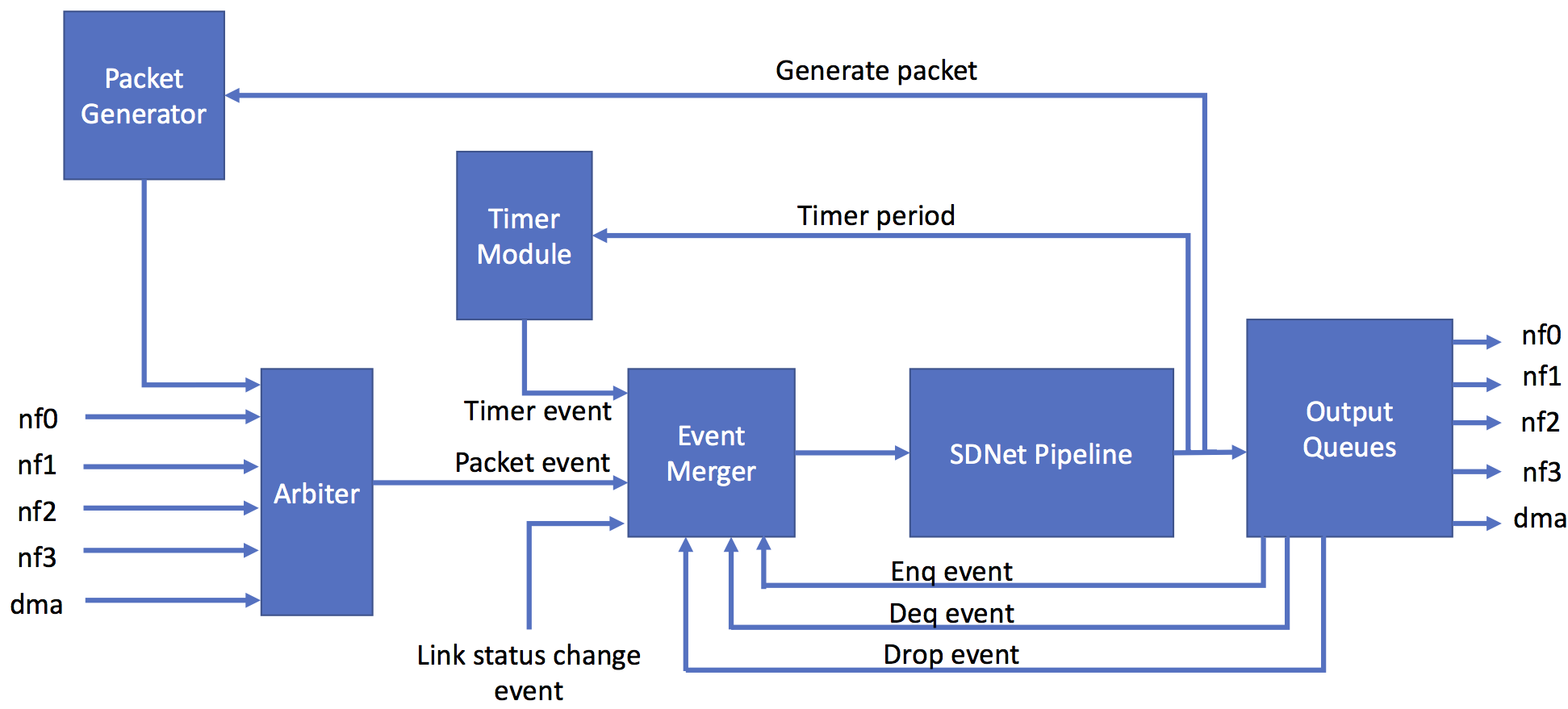
Recall that the SDNet Pipeline is the HDL implementation of your P4 program. The Event Merger module is responsible for aggregating all simultaneous events into a single “packet” and forwarding the result to the SDNet pipeline. I say “packet” because if there are no ingress packet events then the Event Merger module will generate “ghost packets” with the metadata fields listed below. Ghost packets cannot be forwarded out of the ports, they will always be dropped at the output queues. That being said, a ghost packet can tell the Packet Generator module to generate a packet, which can be forwarded out of the switch.
Every packet that enters the SDNet pipeline comes with the following metadata fields that you can access in your P4 program:
struct sume_metadata_t {
    // request a packet to be generated
    bit<1> gen_packet;
    // *_trigger fields indicate when a particular event has fired
    bit<1> link_trigger;
    bit<1> timer_trigger;
    bit<1> drop_trigger;
    bit<1> deq_trigger;
    bit<1> enq_trigger;
    bit<1> pkt_trigger;
    // Current link status (one-hot)
    bit<4> link_status;
    // time when timer event fired (20ns resolution)
    bit<48> timer_now;
    // period at which timer events are configured to fire (20ns resolution)
    bit<32> timer_period;
    // ports and user metadata for enq/deq/drop events
    port_t drop_port;
    port_t deq_port;
    port_t enq_port;
    bit<32> drop_data;
    bit<32> deq_data;
    bit<32> enq_data;
    // standard metadata fields
    port_t dst_port;
    port_t src_port;
    bit<16> pkt_len;
}
Here is a more detailed description of the above metadata fields:
gen_packet- if this bit is set by the P4 program then the Packet Generator module will generate one 64B packet with an etherType field value of0x2121, all other fields have a value of 0.link_trigger- this bit will be set when one or more links have changed their status (e.g. cable has been unplugged).timer_trigger- this bit will be set if the timer has expired.drop_trigger- this bit will be set whenever a packet is dropped at an output queue as a result of of overflow.deq_trigger- this bit will be set whenever a packet is dequeued from an output queue.enq_trigger- this bit will be set whenever a packet is enqueued into and output queue.pkt_trigger- this bit will be set whenever there is a legitimate packet attached to this thread of execution.link_status- the current link status, one-hot encoded where 1 indicates the link is up and 0 indicates the link is down. The most significant bit corresponds to nf3 and the least significant bit corresponds to nf0.timer_now- the time when the timer event last fired, measured in increments of 20ns.timer_period- the period at which the timer events should fire, measured in increments of 20ns. Initialized to 0 by default, meaning that the timer events should never fire. This can be changed by the P4 program.drop_port- if thedrop_triggerfield is set then this field indicates the output port(s) that dropped the packet, uses the same format as thedst_portfield.deq_port- if thedeq_triggerfield is set then this field indicates the port that just dequeued a packet for transmission, uses the same format as thedst_portfield.enq_port- if theenq_triggerfield is set then this field indicates the port that just enqueued a packet, uses the same format as thedst_portfield.drop_data,deq_data, andenq_data- these are intended to be user defined metadata fields. They serve a dual purpose: (1) whenever a dequeue, drop, or enqueue event fires, the corresponding field will contain the metadata that correponds to the packet that was just dequeued, dropped, or enqueued; (2) the P4 program should overwrite these fields at the end of the pipeline to prepare the current packet for enqueue, drop, and dequeue.pkt_len,src_port,dst_port- the fields have the same functionality as they do in the SimpleSumeSwitch architecture.
We’ve also added support for a new extern called reg_multi_raws that allows P4 programs to perform up to 3 read-modify-write (RMW) operations on a single BRAM-based register array. Only one of the RMW operations is guaranteed to be performed immediately (because that’s all that fits in a single 64B packet time @ 40Gbps), the other two RMW requests are queued and will be performed by the extern whenever it finds spare cycles. If the min size packet is 150B then all 3 RMW operations will be performed atomically for each packet.
Writing Simulations for SUME Event Switch
The general process of setting up and running smiulations for P4 programs that are written for the SUME Event Switch architecture is the same as it is for the SimpleSumeSwitch architecture, with a few minor differences.
The gen_testdata.py script can only be used to test the functionality of the SDNet pipeline within the architecture. This makes it challenging to use it to test programs that use the various events generated by other blocks in the architecture. Here are some recommendations for testing SUME Event Switch programs:
- The Workflow Steps are still exactly the same, but now your effort will shift from step 3 (writing
gen_testdata.py) to step 8 (setting up the SUME simulation). - You do still need to write a
gen_testdata.pyscript that generates at least one applied/expected packet/metadata, but these tests do not need to be comprehensive. The reason for this is because the SDNet simulation generates the configuration writes to populate table entries, which are reused in the SUME simulation. - Once you reach step 8 in the workflow steps, you’ll want to write your own
run.pyscript(s). Yourrun.pyscript should generate the set of packets you want to send through the switch and configure their injection timestamps andtuser_sportfields. Therun.pyscript can also read/write registers within your P4 program. See the sim_switch_2flows example within the fred_basic project. Here is some more information about writing theserun.pyscripts. - After running the SUME simulation as indicated in step 9 of the workflow steps, you’ll see that the
$NF_DESIGN_DIR/testdirectory has been populated with files that contain the expected and logged packets on each port (in AXI grammar format). These are very useful files for debugging purposes. For example, thenf_interface_1_log.aximight look like:
*3082
000a0100000ac966004000000100320000450008010000000008020000000008, ffffffff, 00000000000000000000000004010040, # 12576 ns
0000000000000000000000000000000000000000000000000000000000000200, ffffffff, 00000000000000000000000004010040. # 12580 ns
*84
000a0100000ac966004000000100320000450008010000000008020000000008, ffffffff, 00000000000000000000000004010040, # 12920 ns
0000000000000000000000000000000000000000000000000000000000000200, ffffffff, 00000000000000000000000004010040. # 12924 ns
- You can also run the SUME simulations using the
--guioption to view the simulation waveforms within a Vivado GUI, which can also be a useful way of debugging. For example,$ cd $SUME_FOLDER && ./tools/scripts/nf_test.py sim --major switch --minor 2flows --gui - You will need to connect via VNC to your development machine by first installing a VNC client then starting the VNC server on your development machine:
$ vncserver - Then you should be able to connect to
packet-X.stanford.edu:1from within the VNC client. - Note that you may need to update your VNC server password before starting the server:
$ vncpasswd